Pages

Showing posts with label Basics. Show all posts

Sunday, February 16, 2014

Understanding of AC Signal

AC (Alternating Current) signal is commonly used format in most of the electrical systems. But when it comes to electronics, DC (Direct Current) plays major role. However it is necessary to understand about AC signal.

AC Signal components:


Frequency (f):
AC signal propagates in cyclic form with positive cycle and negative cycle. The measure of how fast this cycle repeats is called as frequency, and it is the inverse of time required to complete a cycle.

Frequency (f) = 1/Time required to complete a cycle

The unit for frequency is Hertz (Hz).

If an AC signal frequency is 50 Hz. Then time required to complete one cycle is T = 1/f =>0.02 Sec.

Average Value:
Average value of an AC signal is zero, because it has both positive and negative peaks.

RMS Voltage (Vrms):
RMS (Root Mean Square) value is the effective value of a varying voltage or current. It can be considered as the equivalent DC value which gives same effect. Multimeter measures the RMS value of AC signal.

Vrms = (1/√2)*Vp = 0.707*Vp

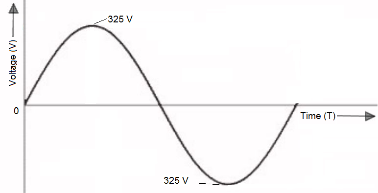
How to draw a 230V AC Signal:
Vrms = 230V
So, Vp = √2*Vrms = √2*230 = 325 V


Tuesday, February 4, 2014

OPAMP Basics

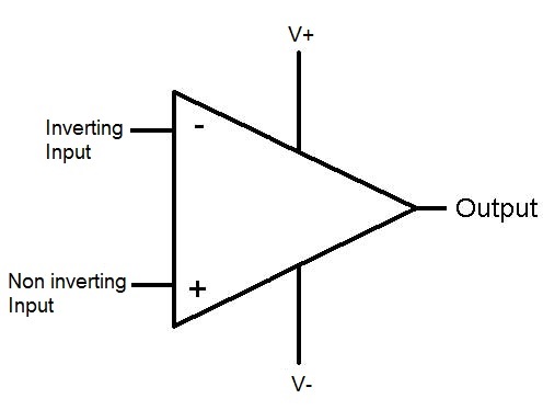
OPAMP (Operational Amplifier) is an Integrated Circuit (IC) designed for Linear Amplification.


Ideal OPAMP Characteristics:
1. Infinite Input Impedance
2. Zero Output Impedance
3. Differential Mode Gain is infinite
4. Common Mode Gain is zero
5. Bandwidth is infinite
6. Slew rate is infinite


Understand the benefits of Ideal OPAMP Characteristics:
  • Infinite Gain because of Infinite input impedance and Zero output impedance
  • No noise amplification as the Common mode gain is zero
  • Amplification of all the frequency ranges from DC to infinite frequency of AC signal as the Bandwidth is infinite


OPAMP Golden Rules:
1. Inputs draw no current
2. Output does whatever is necessary to maintain the two inputs at equal voltages


In every Opamp analysis the above rules are applicable.


OPAMP Circuits:
1. Inverting Amplifier
2. Non-Inverting Amplifier
3. Voltage Follower
4. Comparator
5. Differential Amplifier
6. Integrator
7. Differentiator
8. Summation Amplifier
9. Instrumentation Amplifier

                                                                                    ......................................This post will be updated.


Monday, January 20, 2014

Resistor basics and its selection

Resistor is a two terminal component. It is mostly used for current limiting, Potential divider, Pull up and Pull down purposes.


Resistor is made up of insulating material such as carbon to restrict the flow of electrons, while doing this it dissipates heat. The resistor will blow up, if the heat dissipation of a resistor is greater than the value it is rated for. 

How to select a resistor?
The below main parameters will be considered while selecting a resistor,

1. Resistor value
2. Power Rating
3. Package (SMD or Through hole)

Resistor Value:
A resistor is chosen based on the voltage drop across it and the current it should allow.

If the required voltage drop between the two nodes is 2V and the current in that loop is 4mA then the resistor to be placed between those two nodes is 0.5K 

R=V/I=2V/4mA=0.5K

Power Rating of a resistor:
Power rating of a resistor is based on the current passing through it. Suppose if a resistor with the value of 10K needs to allow 10mA current safely without over heating, then the power rating of that resistor should be 1W.

P=I2R=10mA*10mA*10K=1W

Package:
Package of a resistor depends upon the board size, frequency of operation, soldering and power rating requirement.

SMD is suitable for small size board, higher frequency of operation, automated machine soldering. 

Through hole is suitable for bigger size board, board with lower frequency of operation such as power supply boards and for hand/wave soldering. The higher power rating resistors are available mostly in through hole package only.    

Some of the Leading Manufactures:

Thursday, December 26, 2013

Basic laws of Electronics

This post is about refreshing some of the basics concepts in electronics which is being used by all electronic designers in daily work,

Ohm’s Law:

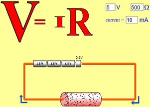
The amount of current through a conductor is directly proportional to the voltage applied across it for any given temperature.


Polarity of Voltage drop:
  • Polarity of voltage drop is determined by the direction of flow of electrons.
  • Negative (-ve) for electron entering
  • Positive (+ve) for electron exiting


Kirchoff’s Voltage Law:
  • Algebraic some of all voltages in a loop is equal to zero.


Kirchoff’s Current Law:

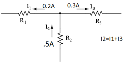
  •  Algebraic some of all currents entering and exiting a node is equal to zero.

 Voltage Divider Rule:
  • The source voltage (V) is divided across the resistors and the voltage drop across a particular resistor (Rx) is given as below,
 Vx = V*(Rx/Rt)

Rt = Total Resistance
Vx = Voltage across the Resistor Rx


Current Divider Rule:
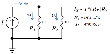
  • The current (I) is divided among branches in a parallel circuit.The current in a particular branch is calculated as below,

In the reference Fig. current through R1 is calculated.

Sunday, May 26, 2013

Introduction to Electronics Engineering

The most important core engineering fields are Civil, Mechanical and Electrical. In ancient days most of the engineering products are based on mechanics only which uses engines, gears, wheels and belts. When the electrical power and motors discovered the usage of electric power took place important place. Once the transistors invented the field of electronics started to get the attention.

The important advantage of electronics is control of  a particular application becomes easy. It increases the compactness, accuracy and precision of the products.

The major classifications of electronics are,

1. Analog
2. Digital
3. Power

Mostly all the real time outputs are analog (amplitude vary with respect to time). This real time analog signals needs to be processed by digital electronics circuitry, so it is necessary to convert those analog signals into digital in order to make them acceptable by digital circuits.

Digital circuits process the inputs and make decisions as per the predefined conditions. If it is necessary then again the digital output needs to be converted to analog to make real time controls.

Power electronics is the part of electronics which deals about the conversion of incoming AC input voltage to DC voltage. (All the semiconductors are operating in DC power).

An Electronics engineer should have basic knowledge of analog, digital and power and he should be expertise on at least one of the fields.

Nowadays since the operating frequency of electronics circuits increases to MHz/GHz an electronic engineer should be aware of EMI/EMC.