Pages

Monday, February 17, 2014

Understanding of Power Conversion Blocks

In any electronics products the power section is one of the vital part and it plays a major role in quality functioning of a board. For most of the electronics product the power source is the AC supply which we have in our house power sockets. So it is necessary to convert this AC power into DC voltage levels which is applicable for the components in the board. Hence it is important to understand about power conversion and the quality it shall have.


Power conversion blocks:


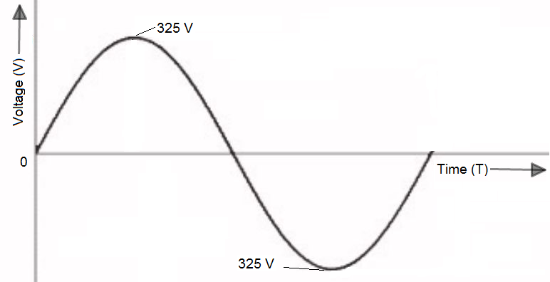
The high AC voltage (230V/110V) is given to a step down transformer and it is reduced to lower level depending upon the desired DC output level. The step down transformer shall have appropriate turns ratio - to convert 240VAC into 12VAC, turns ratio of 240/12 = 20:1 shall be used. But if the desired DC level is 12V then the reduced AC voltage shall be chosen as 15V, this slightly higher level is required to compensate losses which will occur in subsequent steps.  


The stepped down AC voltage is given to rectifier to convert AC into DC voltage. The diode based rectifiers are normally used, the popular one is wheatstone bridge full wave rectifier. The resultant DC voltage is unsmoothed one which means the output level is not a constant one and it will vary within a certain limits.


The unsmoothed output is converted into smoothed DC voltage by filtering stage. The resultant output DC voltage is similar to straight line with certain level and with very low variation.


The resultant filtered DC voltage is used to power the electronic boards with the use of regulators or DC DC converter based on the requirements.         

Sunday, February 16, 2014

Understanding of AC Signal

AC (Alternating Current) signal is commonly used format in most of the electrical systems. But when it comes to electronics, DC (Direct Current) plays major role. However it is necessary to understand about AC signal.

AC Signal components:


Frequency (f):
AC signal propagates in cyclic form with positive cycle and negative cycle. The measure of how fast this cycle repeats is called as frequency, and it is the inverse of time required to complete a cycle.

Frequency (f) = 1/Time required to complete a cycle

The unit for frequency is Hertz (Hz).

If an AC signal frequency is 50 Hz. Then time required to complete one cycle is T = 1/f =>0.02 Sec.

Average Value:
Average value of an AC signal is zero, because it has both positive and negative peaks.

RMS Voltage (Vrms):
RMS (Root Mean Square) value is the effective value of a varying voltage or current. It can be considered as the equivalent DC value which gives same effect. Multimeter measures the RMS value of AC signal.

Vrms = (1/√2)*Vp = 0.707*Vp

How to draw a 230V AC Signal:
Vrms = 230V
So, Vp = √2*Vrms = √2*230 = 325 V


Monday, February 10, 2014

Inverting Amplifier Gain Analysis


This is a constant gain amplifier with negative feedback where the input signal is applied to the inverting terminal of the opamp.  The resultant output is inverted.


As per Kirchoff’s Current Law,

I + If = Ii

Opamp input current is Zero i.e Ii = 0

I + If = 0

If Vi is the voltage at the inverting input terminal,

(Vs - Vi)/Ri + (Vo - Vi)/Rf = 0

Opamp input voltages are always equal, ∴ Vi = 0, because non inverting input terminal is connected to ground.

Vs/Ri + Vo/Rf = 0

Vo/Vi = -Rf/Ri

∴ The gain of inverting amplifier is A = -Rf/Ri

Tuesday, February 4, 2014

OPAMP Basics

OPAMP (Operational Amplifier) is an Integrated Circuit (IC) designed for Linear Amplification.


Ideal OPAMP Characteristics:
1. Infinite Input Impedance
2. Zero Output Impedance
3. Differential Mode Gain is infinite
4. Common Mode Gain is zero
5. Bandwidth is infinite
6. Slew rate is infinite


Understand the benefits of Ideal OPAMP Characteristics:
  • Infinite Gain because of Infinite input impedance and Zero output impedance
  • No noise amplification as the Common mode gain is zero
  • Amplification of all the frequency ranges from DC to infinite frequency of AC signal as the Bandwidth is infinite


OPAMP Golden Rules:
1. Inputs draw no current
2. Output does whatever is necessary to maintain the two inputs at equal voltages


In every Opamp analysis the above rules are applicable.


OPAMP Circuits:
1. Inverting Amplifier
2. Non-Inverting Amplifier
3. Voltage Follower
4. Comparator
5. Differential Amplifier
6. Integrator
7. Differentiator
8. Summation Amplifier
9. Instrumentation Amplifier

                                                                                    ......................................This post will be updated.


Monday, January 20, 2014

Resistor basics and its selection

Resistor is a two terminal component. It is mostly used for current limiting, Potential divider, Pull up and Pull down purposes.


Resistor is made up of insulating material such as carbon to restrict the flow of electrons, while doing this it dissipates heat. The resistor will blow up, if the heat dissipation of a resistor is greater than the value it is rated for. 

How to select a resistor?
The below main parameters will be considered while selecting a resistor,

1. Resistor value
2. Power Rating
3. Package (SMD or Through hole)

Resistor Value:
A resistor is chosen based on the voltage drop across it and the current it should allow.

If the required voltage drop between the two nodes is 2V and the current in that loop is 4mA then the resistor to be placed between those two nodes is 0.5K 

R=V/I=2V/4mA=0.5K

Power Rating of a resistor:
Power rating of a resistor is based on the current passing through it. Suppose if a resistor with the value of 10K needs to allow 10mA current safely without over heating, then the power rating of that resistor should be 1W.

P=I2R=10mA*10mA*10K=1W

Package:
Package of a resistor depends upon the board size, frequency of operation, soldering and power rating requirement.

SMD is suitable for small size board, higher frequency of operation, automated machine soldering. 

Through hole is suitable for bigger size board, board with lower frequency of operation such as power supply boards and for hand/wave soldering. The higher power rating resistors are available mostly in through hole package only.    

Some of the Leading Manufactures:

Monday, January 13, 2014

Introduction to SPICE-Electronic Circuit Simulation

SPICE-Simulation Program for Integrated Circuit Emphasis


SPICE is an Electronic circuit simulator used to verify/predict circuit behaviors. It was developed at the electronic research lab of University of California, Berkeley.


A circuit must be presented to SPICE in the form of netlist. Netlist is a text description of all circuit elements and their corresponding connections.


Simulation tools allows user to draw circuit schematics and automatically translate the circuit diagrams into netlist.


SPICE Model:
Text description of a circuit component used by the SPICE simulator. The extension for the SPICE model file may be in .cir/.mod. .lip is library of .mod files.


The model files can be obtained from corresponding part manufacturer


Model file for Resistor:
Rname n1 n2 value
R120    2   3    100


Analysis using SPICE:
1. DC Analysis
2. AC Analysis
3. Transient Analysis
4. Distortion Analysis
5. Noise Analysis


Some of the Popular Simulation Tools:
1. PSPICE from Cadence
2. Multisim from National Instruments
3. TINA from Design Soft
4. Saber from Synopsys
5. LTSpice from Linear


Sunday, January 5, 2014

Electronic Components Introduction

This post will give introduction to electronic parts which are mostly used in any of the electronic circuit. Elaborate description of each parts will be posted in separate posts.  


1. Resistor (R)
Resistor is a two terminal component. It is mostly used for current limiting, Potential divider, Pull up and Pull down purposes. It is made up of different material and it is available in different packages,termination styles. Based on the requirement such as SMD/Through hole, tolerance and power rating a particular package can be selected.


2. Inductor (L):
Inductor is a two terminal component. It opposes the sudden changes in the current flowing across it. It is mostly used for temporary energy storage and filtering purposes.It is made up of different core material and it is available in shielded/unshielded packages,termination styles. Based on the requirement such as usage (Power or Noise Filtering) , Tolerance and Power rating a particular package can be selected.


3. Capacitor (C):
Capacitor is a two terminal component. Capacitor stores the DC voltage and supply the stored voltage whenever the circuit requires.It is mostly used for filtering and timing circuits.  It is made up of different dielectric materials and it is available in different packages. Based on the application such as Power, High frequency filtering a particular capacitor can be selected.


4. Diode (D):
Diode is basically a two terminal device. Diodes allows the electron flow only in one direction. It is mostly used in Power converters, Regulators, Clipping and Clamping circuits. Based on the doping level and construction there are different types of diodes are available. Depending upon the application (rectifier, regulator) and frequency of the circuits a particular type of diode can be chosen.


5. Transistor (Q):
Transistor is a 3 terminal device and it is the combination of two PN junctions. It is mostly used in switching and amplifier circuits. 


6. MOSFET (Q):
Metal Oxide Semiconductor Field Effect Transistor which is a voltage controlled device. It is mostly used in switching circuits.


7. Sensors
A sensor is a device which can sense a particular physical property such as temperature and produce an output signal. Normally the output signal is analog in nature. There are different types of sensors.
a. Temperature sensor
b. Infrared sensor
c. Image sensor


8. Analog to Digital Converter (ADC):
ADC is an Integrated Circuit (IC) which convert analog voltage into digital data. There are variety of ADCs based on the their architecture. An ADC is chosen mainly based on the resolution it can deliver.


9. Memory
Memory is used to store data in the form of bit (0 or 1).  It can be broadly classified in to types volatile and non-volatile. Volatile memories (Random Access Memory-RAM) don’t retain stored data when the power is OFF. But Non-volatile memories (Read Only Memory-ROM) retain stored data when the power is OFF.


Memories are basically chosen based on the application (temporary storage or permanent storage), size and speed.


10. Microprocessor
Microprocessor accepts digital inputs, process those data in the Central Processing Unit (CPU) as per the predefined sequence (program) and delivers digital output. Microprocessor have no inbuilt memory to store program hence it requires external memory.


11. Microcontroller
Microprocontroller is similar to Microprocessor but the main difference is it has inbuilt memory to store program. Normally the processing power is less in Microcontroller when compared with Microprocessor.